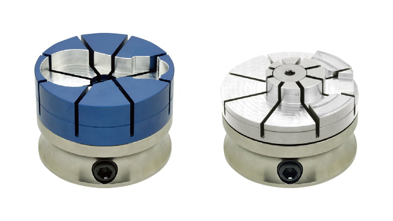
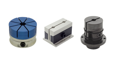
Form Holding Clamps with a machinable jaw are perfect for irregular-shaped workpieces.
Simple workholding on external/internal form eliminates the need for custom fixtures.
Product Video
External Form Holding
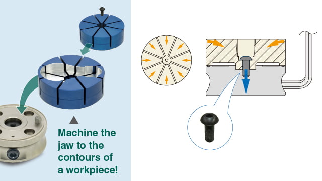
Clamping stroke: 0.6mm in diameter
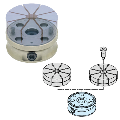
The cam cylinder is tightened, the central bottom part of the jaw is pulled down.
At the same time the 8 jaw sections tilt toward the center for clamping.
Clamping Force
| Jaw Diameter | Max. Clamping Force |
|---|---|
| φ65 | 4.5kN |
| φ90 | 7kN |
| φ120 | 10kN |
| φ160 | 12kN |
Internal Form Holding
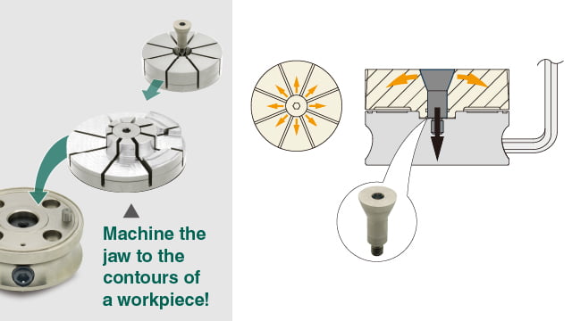
Clamping stroke: 0.6mm in diameter
The cam cylinder is tightened, the tapered screw is pulled down.
At the same time the 8 jaw sections expand for clamping.
Clamping Force
| Jaw Diameter | Max. Clamping Force |
|---|---|
| φ65 | 4.5kN |
| φ90 | 7kN |
| φ120 | 10kN |
| φ160 | 10kN |
Application Example
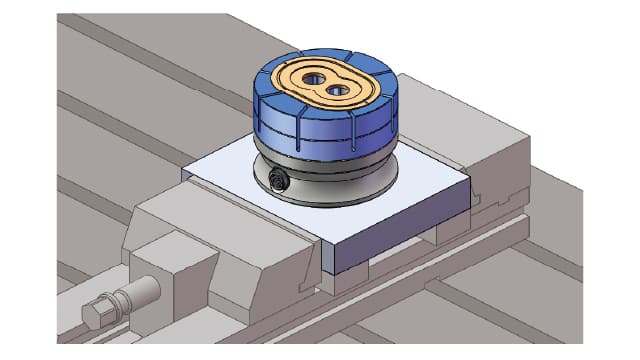
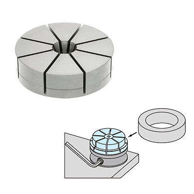
Clamping Low Profile Workpiece
Internal Form Holding Jaw
Can clamp thin workpiece by distributing the clamping force through 8 jaw sections.
Note to controll the tightening torque using adequate tools in reference to the data provided by the performance curve.
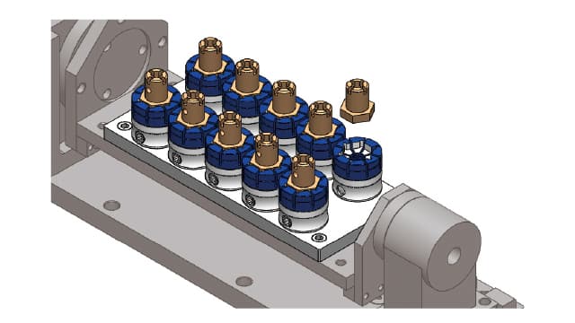
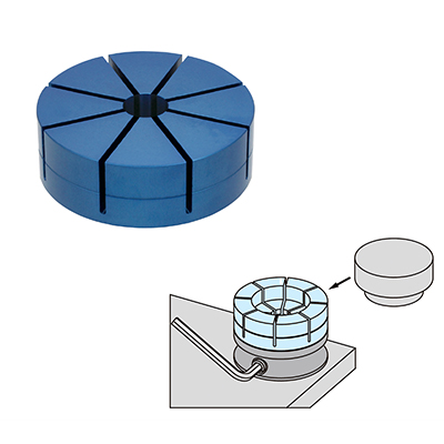
Multiple Piece Clamping
External Form Holding Jaw
Small cylindrical body allows the multi-piece clamping in limited space.
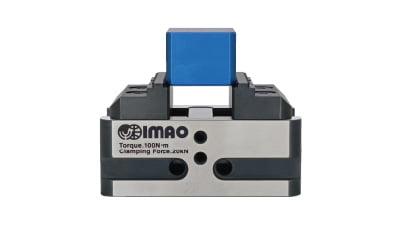
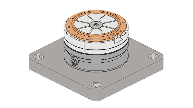
Fixture for Temporal Job
External Form Holding Jaw
Can be mounted on the existing vise by attaching the clamp on plate.
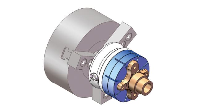
Fixture for Turning Lathe
External Form Holding Jaw
Can clamp odd shape that a chuck does not clamp.
Case Study
CASE 1 Multiple workholding on 5-axis machining center with compact OD clamps!
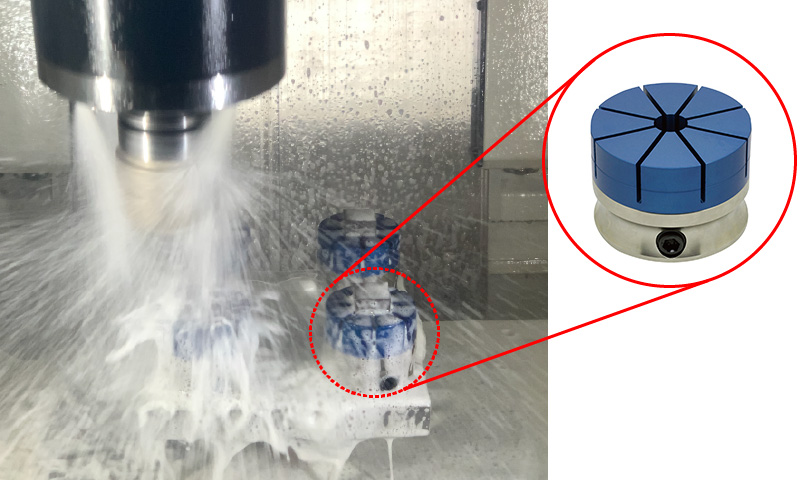
KINKI KOGYO inc. who produces hydraulic cylinder components and various other metal parts, uses IMAO's Form Holding Clamps for various workpieces on their 5-axis machining center. This machining center was introduced to perform fully automated machining, and used to machine hydraulic cylinder parts made of steel and stainless steel.
In the past, only a single workpiece could be clamped using several types of vises or dedicated fixtures. This required them to purchase a large number of vises, which was expensive and also time consuming to set up.
To solve this problem, KINKI KOGYO introduced Form Holding Clamps. They placed four clamps onto one fixture plate to clamp multiple workpieces at a time. This allowed them to increase machine operating time at night.
KINKI KOGYO has plans to replace the jaws to clamp various types of workpieces. They are satisfied with the high clamping force of Form Holding Clamps which is resulting from the collet-shaped design. They are also pleased with its compact size that allows multiple installations, and the flexibility that can clamp both inside and outside of workpieces just by changing the jaws.
Lineup
CP125
FORM HOLDING CLAMPS
CP126
JAWS FOR EXTERNAL FORM HOLDING
CP127
JAWS FOR INTERNAL FORM HOLDING
You may also like
Machinable Collet Clamps
Mechanical / pneumatic collets hold any external shapes
Learn More about Machinable Collet Clamps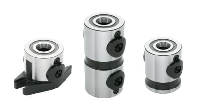
Modular Pull Clamping System
Precise 5-axis pull clamps with clear tool access
Learn More about Modular Pull Clamping System