FAQs about Knob-Locking Pins
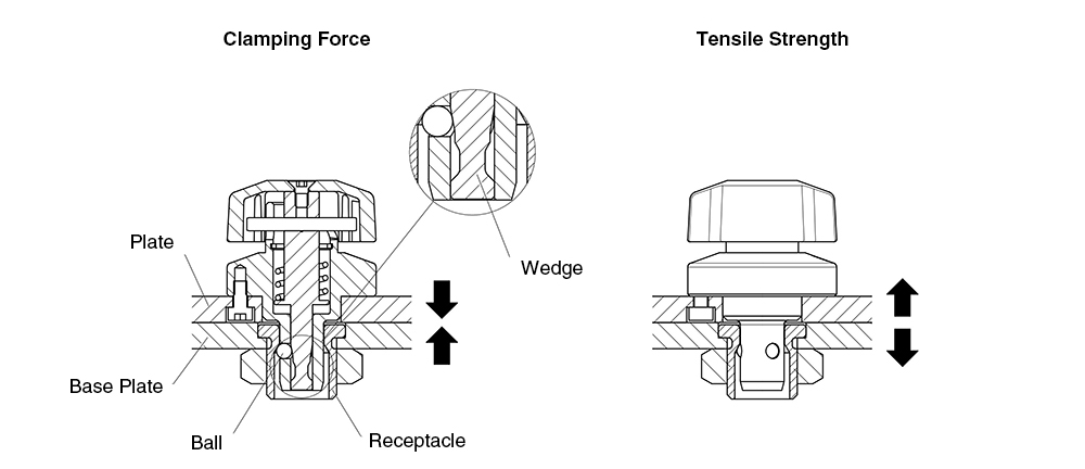
Clamping force refers to the force generated when the balls pushed outward by the wedge contact the tapered surface inside the receptacle, pulling the plate inward.
If a tensile load exceeding the clamping force is applied, a gap may occur. However, the holding force refers to the ability to maintain the gap between the plates within 0.1 mm.
Tensile strength refers to the maximum load that the clamp can withstand when the plate is pulled away from the base.
Even when a tensile load exceeding the clamping force is applied, a gap may occur between the plates, but the wedge structure minimizes the gap.
Please refer to the technical data of each product below for details.
| Series | Size | Clamping Force (N) | Holding Force (N) | Tensile Strength at Failure (N) |
|---|---|---|---|---|
| QCWE | 0625-10 | 30 | 90 | 500 |
| 1034-14 | 50 | 150 | 1500 | |
| 1034-20 |
Yes.
This product can be used in applications subject to offset (moment) loads.
Please refer to the PDF below for guidelines on load calculations, gap generation, and precautions regarding product failure before determining suitability.
No.
The Mechanical Strength values do not include a safety factor.
These values represent the load levels at which failure can occur and should not be considered allowable loads.
| Series | Size | Shear Strength at Failure (N) | Tensile Strength at Failure (N) |
|---|---|---|---|
| QCWE | 0625-10 | 3000 | 500 |
| 1034-14 | 9000 | 1500 | |
| 1034-20 |
The operating torque is very low because the knob is pulled downward by the spring during clamping.
The knob height differs between the clamped and unclamped positions.
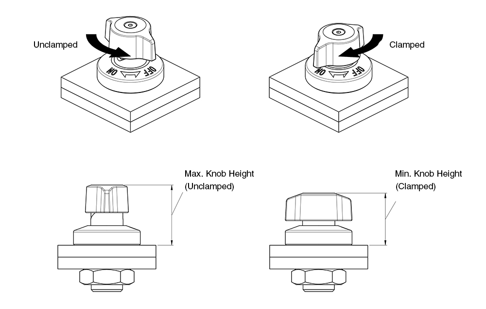
Please refer to the table below for the typical operating torque and knob height.
| Series | Size | Operating Torque (N·m) | Knob Height (Unclamped) | Knob Height (Clamped) |
|---|---|---|---|---|
| QCWE QCWE-SUS |
0625-10 | 0.2 | 24.5 | 21.5 |
| 1034-14 | 0.3 | 31 | 26.5 | |
| 1034-20 |
Note: The operating torque shown above applies to rotation from ON to OFF and is lower when rotating from OFF to ON.
Durability testing is conducted under no-load conditions, focusing on repeated clamping and unclamping of the clamper.
The results of the durability tests are shown below for reference when evaluating product suitability.
| Series | Durability Test Cycles |
|---|---|
| QCWE QCWE-SUS |
30,000 cycles |
No.
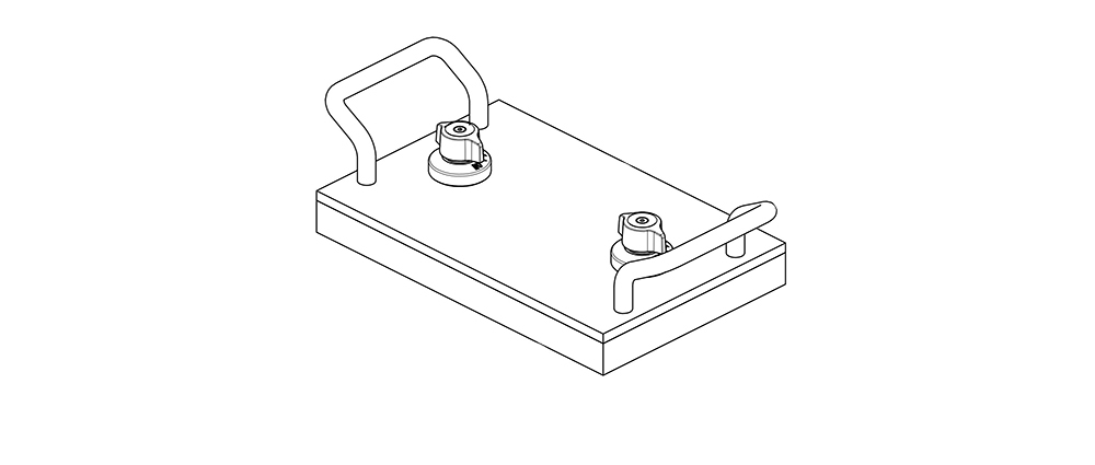
Lifting the knob vertically while the unit is clamped will release the clamp and should be avoided.
When replacing plates or attachments, it is recommended to provide a separate handle designed for attachment and removal.
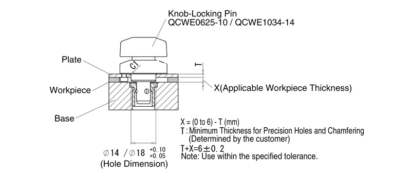
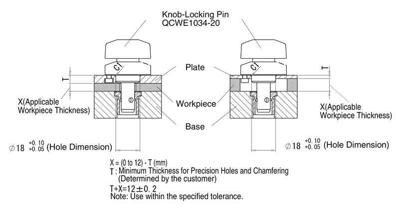
Yes, provided that the combined thickness of the workpiece and the mounting plate is within the T dimension specified in the catalog (tolerance: ±0.2 mm).
However, inserting a workpiece reduces the thickness of the mounting plate. Therefore, it is recommended to ensure sufficient plate thickness to allow for precision holes and chamfering.
As the required mounting thickness varies depending on the clamp model, please refer to the figure below for details.
Yes.
When mounted on a vertical surface, the moment load generated by the weight of the workpiece may cause a gap between the plates.
When used in a hanging position, a gap may occur if the weight of the workpiece exceeds the clamping force.
Please refer to the table below for details.
| Series | Size | Clamping Force (N) | Shear Strength at Failure (N) | Tensile Strength at Failure (N) |
|---|---|---|---|---|
| QCWE | 0625-10 | 30 | 3000 | 500 |
| 1034-14 | 50 | 9000 | 1500 | |
| 1034-20 |
When using the product in a hanging position or on a vertical surface, be sure to implement adequate safety measures.
Yes.
By using the optional spacer, the product can be used with plates that are 3 mm thick or greater but less than 6 mm.
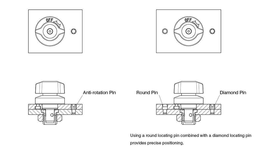
Yes, the product can be used with a single clamp and receptacle set.
However, we recommend using locating pins to prevent the plate from rotating.