FAQs about Retractable Quarter Turn Clamps
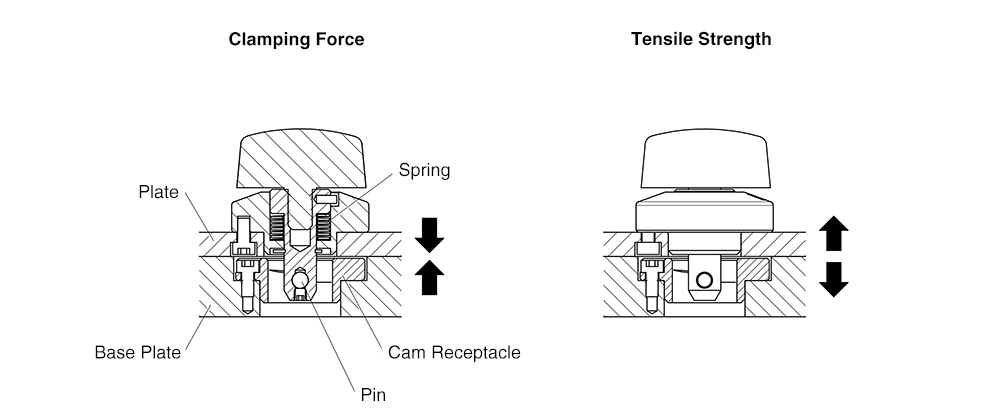
Clamping force refers to the force generated when the pin contacts the cam in the Cam Receptacle, compressing the spring and pulling the plate inward.
Because this product uses a spring clamping mechanism, a gap may occur if a tensile load exceeding the clamping force is applied. Therefore, the holding force should be considered equal to the clamping force.
Tensile strength refers to the maximum load that the clamp can withstand when the plate is pulled away from the base.
Please refer to the technical data of each product below for details.
| Series | Size | Clamping Force (N) | Tensile Strength at Failure (N) | Max. Gap Between Plates (mm) |
|---|---|---|---|---|
| QCTH QCTHL QCTHH |
0525-10 | 60 | 1200 | 1.5 |
| 0834-14 | 90 | 2600 | 1.2 | |
| 0834-20 | ||||
| QCTHA | 0525-10 | 60 | 1200 | 0.7 |
| 0834-14 | 90 | 400 | 1.1 | |
| QCTHA-SUS | 0525-10 | 60 | 1200 | 0.7 |
| 0834-14 | 90 | 1.1 | ||
| QCTHS QCTHS-S |
0825-20 | 250 | 1100 | 1.0 |
| 0834-20 | 400 | 1600 | 1.5 | |
| QCTHSA QCTHSA-S |
0825-20 | 250 | 1600 | 1.2 |
| 0834-20 | 400 |
Yes.
This product can be used in applications subject to offset (moment) loads.
Please refer to the PDF below for guidelines on load calculations, gap generation, and precautions regarding product failure before determining suitability.
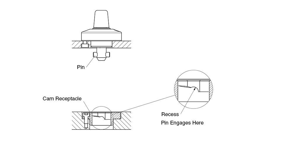
Yes.
When the product is clamped, the pin of the clamp mechanism engages with the recess inside the cam receptacle. As a result, the clamp will not be released by vibration alone.
No.
The Mechanical Strength values do not include a safety factor.
These values represent the load levels at which failure can occur and should not be considered allowable loads.
| Series | Size | Shear Strength at Failure (N) | Tensile Strength at Failure (N) |
|---|---|---|---|
| QCTH QCTHL QCTHH |
0525-10 | 1800 | 1200 |
| 0834-14 | 3200 | 2600 | |
| 0834-20 | |||
| QCTHA | 0525-10 | 1800 | 1200 |
| 0834-14 | 3200 | 400 | |
| QCTHA-SUS | 0525-10 | 1800 | 1200 |
| 0834-14 | 3200 | ||
| QCTHS QCTHS-S |
0825-20 | 4800 | 1100 |
| 0834-20 | 1600 | ||
| QCTHSA QCTHSA-S |
0825-20 | 3000 | 1600 |
| 0834-20 |
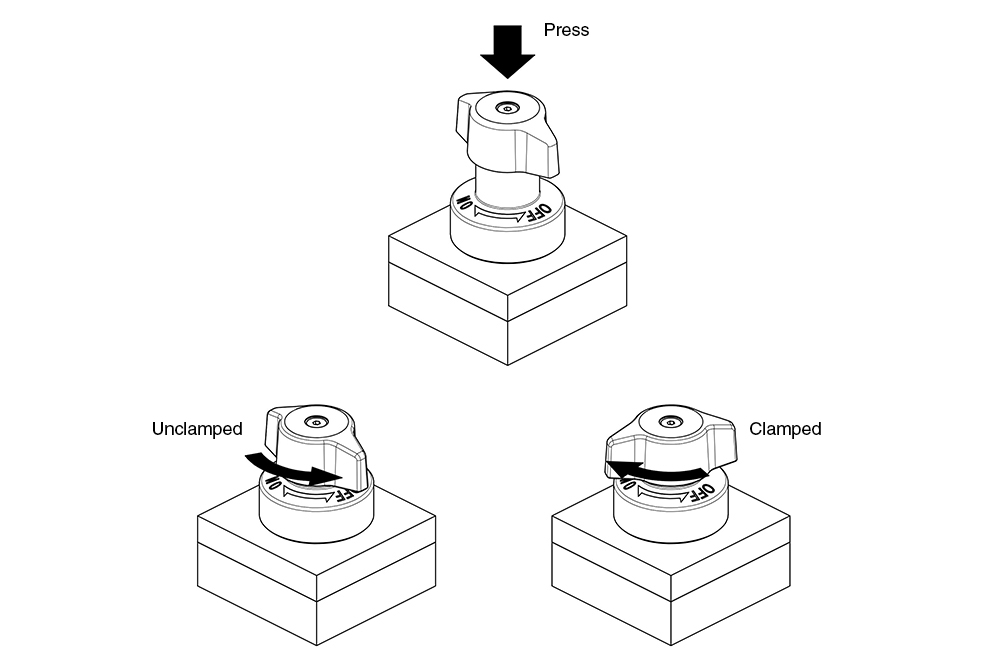
Push-down force refers to the force required to push the knob down and insert the pin into the cam receptacle. Operating torque refers to the torque required to turn the knob to the ON/OFF position.
Please refer to the table below for the push-down force and typical operating torque.
| Series | Size | Knob Push-down Force (N) | Operating Torque (N·m) |
|---|---|---|---|
| QCTHA | 0525-10 | 2.4 | 0.4 |
| 0834-14 | 4.6 | 0.5 | |
| QCTHSA | 0825-20 | 3.3 | 0.6 |
| 0834-20 | 1 |
Durability testing is conducted under no-load conditions, focusing on repeated clamping and unclamping of the clamper.
The results of the durability tests are shown below for reference when evaluating product suitability.
| Series | Durability Test Cycles |
|---|---|
| QCTH | 30,000 cycles |
| QCTHL | |
| QCTHH | |
| QCTHA | |
| QCTHS | |
| QCTHSA |
Due to differences in internal structure and available space, the smaller steel Retractable type incorporates stronger load-bearing components.
As a result, its tensile strength is higher than that of the larger steel type.
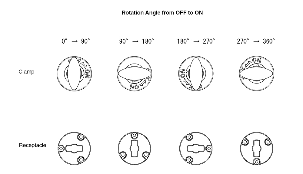
The ON/OFF position of the clamp is determined by the mounting orientation of the clamp and the receptacle.
Please refer to the illustration below for the correct mounting orientation.
Yes.
When mounted on a vertical surface, the moment load generated by the weight of the workpiece may cause a gap between the plates.
When used in a hanging position, a gap may occur if the weight of the workpiece exceeds the clamping force.
Please refer to the table below for details.
When using the product in a hanging position or on a vertical surface, be sure to implement adequate safety measures.
| Series | Size | Clamping Force (N) | Shear Strength at Failure (N) | Tensile Strength at Failure (N) | Max. Gap Between Plates (mm) |
|---|---|---|---|---|---|
| QCTH QCTHL QCTHH |
0525-10 | 60 | 1800 | 1200 | 1.5 |
| 0834-14 | 90 | 3200 | 2600 | 1.2 | |
| 0834-20 | |||||
| QCTHA | 0525-10 | 60 | 1800 | 1200 | 0.7 |
| 0834-14 | 90 | 3200 | 400 | 1.1 | |
| QCTHA-SUS | 0525-10 | 60 | 1800 | 1200 | 0.7 |
| 0834-14 | 90 | 3200 | 1.1 | ||
| QCTHS | 0825-20 | 250 | 4800 | 1100 | 1.0 |
| 0834-20 | 400 | 1600 | 1.5 | ||
| QCTHSA | 0825-20 | 250 | 3000 | 1600 | 1.2 |
| 0834-20 | 400 |
Yes.
By using the optional spacer, the product can be used with plates that are 3 mm thick or greater but less than 6 mm.
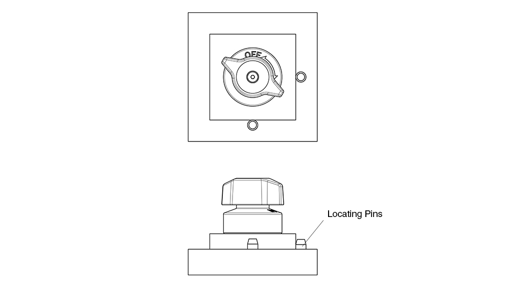
Yes, the product can be used with a single clamp and receptacle set.
However, we recommend using locating pins to prevent the plate from rotating.