FAQs about Shaft Coupling Clamps
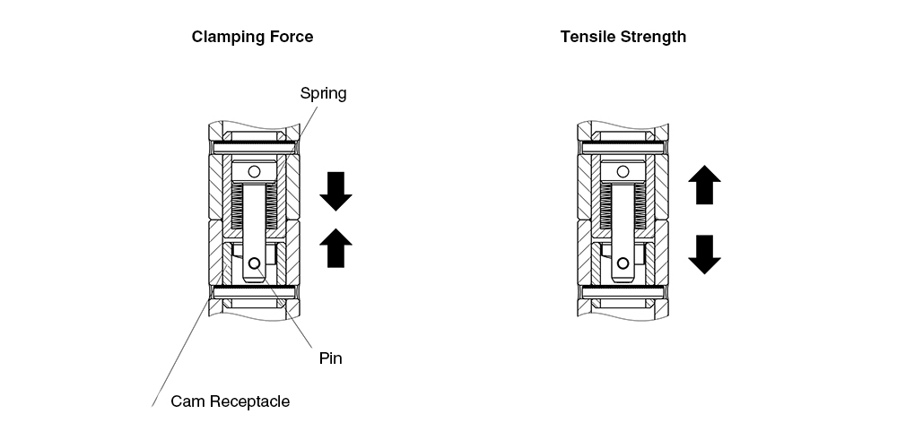
Clamping force refers to the force generated when the pin contacts the cam surface inside the shaft coupling case, compressing the spring and pulling the case inward.
Because this product uses a spring clamping mechanism, a gap may occur if a tensile load exceeding the clamping force is applied. Therefore, the holding force should be considered equal to the clamping force.
Tensile strength refers to the maximum load that the shaft coupling can withstand when the joint is pulled.
Please refer to the technical data of each product below for details.
| Part Number | Clamping Force (N) | Tensile Strength at Failure (N) | Max. Gap Between Plates (mm) |
|---|---|---|---|
| QCSJ0514A | 90 | 1200 | 1.8 |
Yes.
This product can be used in applications subject to offset (moment) loads.
Please refer to the PDF below for guidelines on load calculations, gap generation, and precautions regarding product failure before determining suitability.
Yes, provided that no force is applied in the rotational direction.
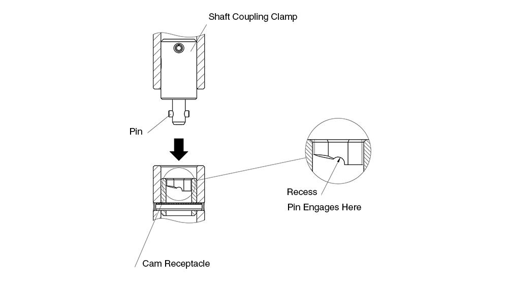
When locked, the pin of the Shaft Coupling Clamp engages with the recess inside the receptacle.
As a result, the clamp will not be released by vibration alone.
If there are concerns regarding actual operating conditions, we recommend that users perform their own testing to determine suitability.
Operating torque refers to the torque required to lock and unlock the shaft.
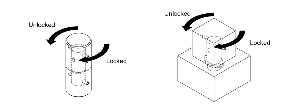
The operating torque may vary depending on the shaft material and the surface roughness of the contacting surfaces.
Please refer to the table below for the typical operating torque.
| Part Number | Shaft Conditions for Torque Testing | |||
|---|---|---|---|---|
| Material / Finish | Shaft Size | Surface Roughness | Operating Torque (N·m) | |
| QCSJ0514A | Aluminum Anodized |
□20mm | Ra 6.3 | 0.3 |
| QCSJS0822A | φ40mm | 2.1 | ||
No.
The Mechanical Strength values do not include a safety factor.
These values represent the load levels at which failure can occur and should not be considered allowable loads.
| Part Number | Shear Strength at Failure (N) | Tensile Strength at Failure (N) |
|---|---|---|
| QCSJ0514A | 1800 | 1200 |
Durability testing is conducted under no-load conditions, focusing on repeated clamping and unclamping of the clamper.
The results of the durability tests are shown below for reference when evaluating product suitability.
| Part Number | Durability Test Cycles |
|---|---|
| QCSJ0514A | 30,000 cycles |
Yes.
When mounted on a vertical surface, the moment load generated by the weight of the workpiece may cause a gap between the plates.
When used in a hanging position, a gap may occur if the weight of the workpiece exceeds the clamping force.
Please refer to the table below for details.
| Part Number | Clamping Force (N) | Shear Strength at Failure (N) | Tensile Strength at Failure (N) | Max. Gap Between Plates (mm) |
|---|---|---|---|---|
| QCSJ0514A | 90 | 1800 | 1200 | 1.8 |
When using the product in a hanging position or on a vertical surface, be sure to implement adequate safety measures.