FAQs about Ball-Lock Clamping Receptacles
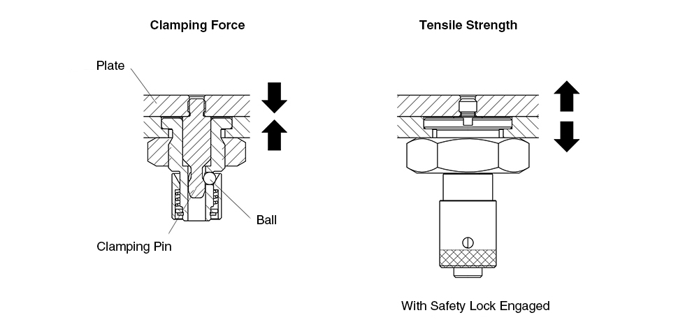
Clamping force refers to the force generated when three balls pull in the Clamping Pin, pulling the plate inward.
For lock-equipped models, tensile strength refers to the maximum load that can be withstood when the Ball-lock Clamp is pulled in the locked state.
For non-locking models, the clamp will disengage if a force exceeding the clamping force is applied.
If a force exceeding the clamping force is applied, a gap may occur between the plates.
Please refer to the technical data of each product below for details.
| Part Number | Clamping Force (N) | Tensile Strength (N) |
|---|---|---|
| QCBA0816A | 7 | 7 |
| QCBA0816B | 15 | 15 |
Note: If a tensile load exceeding the clamping force is applied, the clamp may disengage.
Safety Lock
| Part Number | Clamping Force (N) | Tensile Strength at Failure (N) | Max. Gap Between Plates (mm) |
|---|---|---|---|
| QCBAS0820A | 7 | 1800 | 0.4 |
| QCBAS0820B | 15 |
Note: The tensile strength value applies when the safety lock is engaged.
No.
The Mechanical Strength values do not include a safety factor.
These values represent the load levels at which failure can occur and should not be considered allowable loads.
| Part Number | Shear Strength at Failure (N) | Tensile Strength (N) |
|---|---|---|
| QCBA0816A | 1800 | 7 |
| QCBA0816B | 15 |
Safety Lock
| Part Number | Shear Strength at Failure (N) | Tensile Strength at Failure (N) |
|---|---|---|
| QCBAS0820A | 1800 | 1800 |
| QCBAS0820B |
Note: The tensile strength value applies when the safety lock is engaged.
Durability testing is conducted under no-load conditions, focusing on repeated clamping and unclamping of the clamper.
The results of the durability tests are shown below for reference when evaluating product suitability.
| Series | Durability Test Cycles |
|---|---|
| QCBA | 30,000 cycles |
| QCBAS |
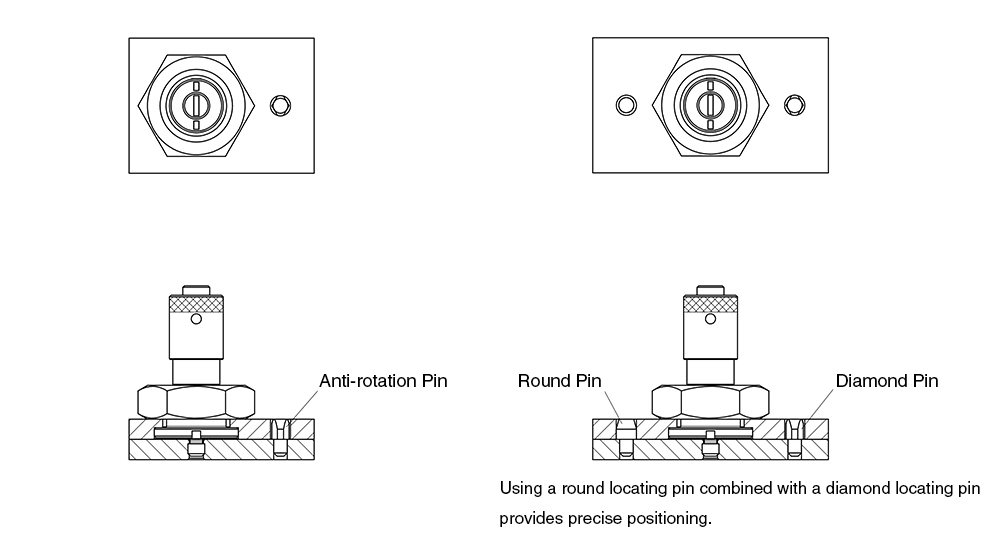
Yes, the product can be used with a single receptacle and clamping pin set.
However, we recommend using locating pins to prevent the plate from rotating.